
IFCout-Cloud Help
IFCout Cloud is a powerful add-on for AutoCAD Plant 3D, Advance Steel, and other AutoCAD verticals, designed to streamline the export of drawings to IFC format. Leveraging the proven IFCout desktop engine, it enables batch processing outside of the AutoCAD environment for plant components, structural members, and native entities.
Key features include:
-
Versatile Formats: Supports exports to IFC2x2, IFC2x3, and IFC4.
-
Flexible Storage: Process drawings stored locally or via cloud services such as Autodesk Docs, Google Drive, and OneDrive. Output files can similarly be saved to local or cloud destinations.
-
Automation: Includes a built-in scheduler to run automated, recurring export tasks at designated times.
Necessary Steps to run the app from scratch
1- You must have AutoCAD installed on your local machine with any of the following versions: 2026,2025, 2024 or 2023.
2- To use the Cloud, you must map Autodesk Drive, Autodesk Docs or any other cloud service to your local machine. For Autodesk Drive or Autodesk Docs more information, visit:
3- You must be signed into your Autodesk 360 Account in AutoCAD.
4- For IFCout Cloud downloaded from Autodesk App Store, you must register your online user ID within AutoCAD. After installing IFCout Cloud, run AutoCAD and type in this command: MDCSETUSERID , a message will appear to confirm this registration.

Quick Tutorial
When you run IFCout Cloud, the MAIN window appears as seen below:

Important Definitions:
Configuration File:
A configuration file stores all the essential data required to execute a batch export. This includes the selection of drawing files, the designated output location for the IFC files, and various settings that will be detailed in the following sections. Note that establishing at least one working folder is a mandatory requirement for this process.
Working Folder:
Working folders hold all your defined and saved configuration files
Schedules:
Task Schedules allow you to automate your exports by running configuration files at specific times and frequencies based on your custom settings. Schedules can be modified, deleted, enabled and disabled at anytime.
AutoCAD Command:
In AutoCAD PLANT3D you can use the following command to extract and save project specific properties to a file. You can then open this file to select components properties you wish to export as well. This command is:
MDCEXPORTPROJECT
Settings
Getting Started with IFC out Cloud
Initial Setup:
When you launch IFCout Cloud for the first time, you will be prompted to enter your credentials. Following login, you must define your Working Folder. This directory is critical as it stores all configuration, schedule, and log files required for the export process. You can update this location at any time using the Browse button.
Navigation and Interface
The application is organized into four primary tabs:
-
Configurations: Create and manually execute export files.
-
Settings: Define the core parameters for each configuration.
-
Schedules: Manage and modify automated task schedules.
-
Logs: Review export history and diagnostic files.
Creating an Export Configuration
Creating a configuration is the essential first step for both manual and scheduled exports.
-
To Begin: Click the New Configuration button and enter a name for your file.
-
Program Source: The application defaults to the target AutoCAD program currently active (e.g., AutoCAD Plant 3D). If you need to change the target program later, use the Update button.
-
Savings: New configurations are automatically saved to your Working Folder.
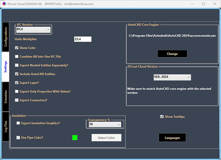
Configuring Settings
Once a configuration is created, you can customize its behavior in the Settings tab:
-
Format & Scale: Select your preferred IFC file format. Use the Units Multiplier to ensure the model scales correctly (e.g., enter 25.4 to convert an inch-based AutoCAD model to millimeters).
-
Core Engine: By default, the app uses the latest installed version of AutoCAD. If you switch to an earlier version, ensure the IFC out Cloud version remains compatible.
-
Preferences: Toggle Tooltips or change the interface Language as needed.
Export Options
-
Visuals: Enable Show Color to include entity colors; use Export Layer to retain AutoCAD layer data.
-
Consolidation: Enable Combine All into one IFC File to merge all models; otherwise, they will export as individual files.
-
Geometry: Use Export Nested Entities Separately to explode blocks. Include AutoCAD Entities ensures basic geometry is exported alongside specialized Plant 3D or Advance Steel objects.
-
Optimization: Export only properties with values prevents empty data fields from cluttering the IFC file.
-
Plant 3D Specifics: You can choose Export Connectors or Insulation. For insulation, you can adjust transparency levels and choose between the pipe color or a dedicated insulation color.
Specify Drawing List

Click The Drawing List Button as shown above. The following dialog box appears.

This dialog box allows you to specify the drawing files you want to add in the selected configuration file.
1- Click the 'Browse to Select Drawings' button. A Window's navigation window appears where you can select the folder where the drawing files are located. All drawing files in the selected folder are then displayed in the 'Existing Drawings' list as shown above. Note that these drawings are only to select from not the actual drawings to be exported to IFC files.
2- Click 'Add All' to add all listed drawings to the actual Drawings to Export list. You can also click the 'Add' button to add only the selected drawings.